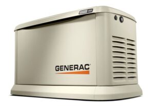
 Before selecting a fuel-gas generator, consideration must be given to the capacity of the existing fuel gas piping and meter. Because generators are typically purchased and installed after a house is built, it is entirely possible the existing piping system will need to be upgraded to handle the added demand of the generator. Where so-called "load diversity" cannot be demonstrated, the fuel gas codes (i.e., International Fuel Gas Code [IFGC] and NFPA 54, National Fuel Gas Code) and your local jurisdictional authority are going to require the piping system be able to support simultaneous operation of all gas appliances attached to the piping system.
Keep in mind: load diversity cannot be claimed where a given appliance can be fired at will. In other words, where nothing inhibits its operation. For example: a homeowner cannot claim their gas furnace is not used during the summertime and therefore insist the contractor eliminate its capacity requirements from the total load. Because the furnace can be fired, even in the summertime, the codes official will normally reject any claim of load diversity. For this reason, calculations and design drawings must be prepared as part of the permit application process.
Sadly, most homeowner's discover the generator they've purchased cannot handle much of their intended electrical load--especially the air conditioning or heat pump and their gas piping (or meter) is often too small to handle the added flow requirements.
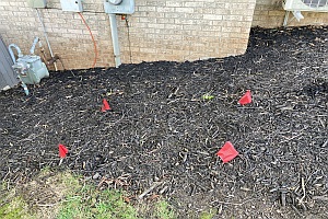
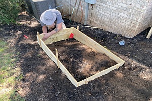
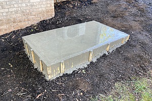
Here, a form is prepared for the generator pad. Before this work is begun, you should contact the local jurisdictional authority to confirm proper setbacks (i.e., separations) are maintained between the gas meter and any electrical supply and distribution equipment. Clearances between the structure and any windows and/or vents must also be maintained.
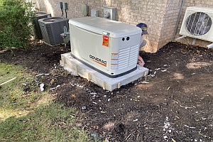
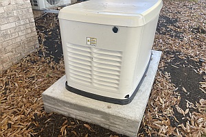
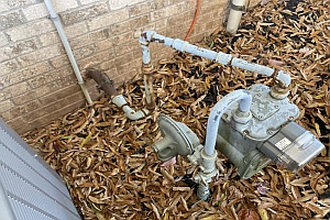
After concrete curing, the generator is placed on the pad. The generator is then connected to the existing fuel gas piping. After the required leak tests and inspection is complete, the piping is coated using a corrosion-resistant paint.
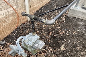
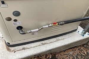
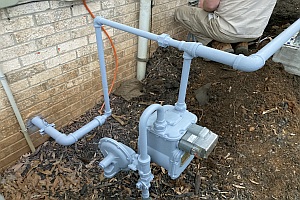
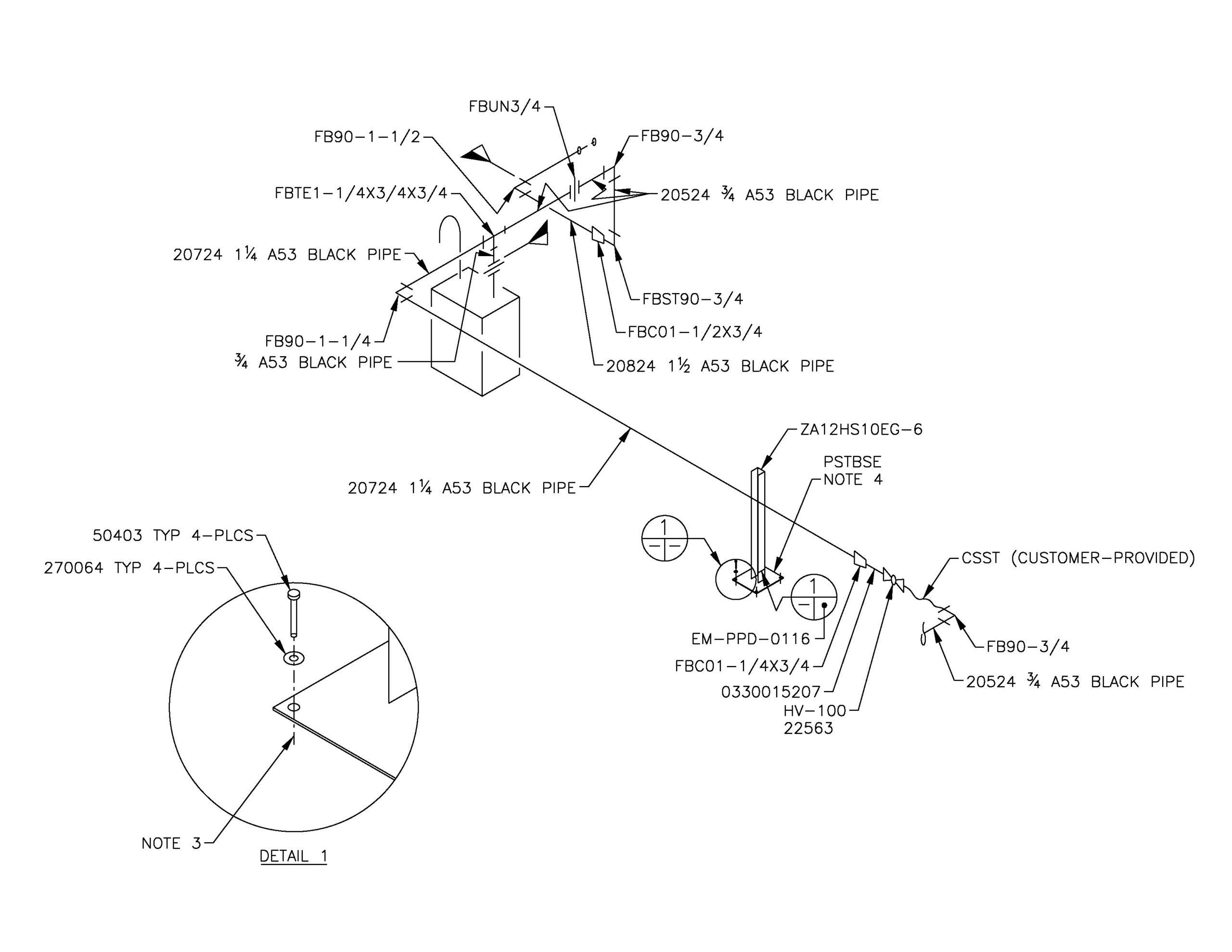
In accordance with the manufacturer's specification, a flexible corrugated stainless steel (CSST) appliance connector is installed between the CSA/UL Listed, ASME B16.44/5G gas isolation valve and the generator. Note the stanchion used to support the gas piping, which is rigidly affixed to the concrete pad using anchors.
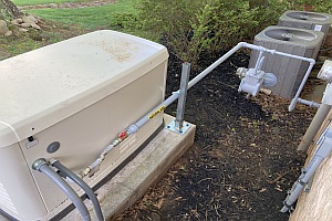
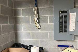
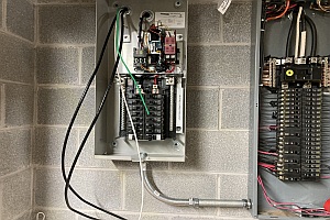
After completing the fuel gas piping, the feeders and control wires are routed through underground raceway, through the exterior wall of the structure and terminated at the transfer switch.
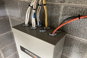
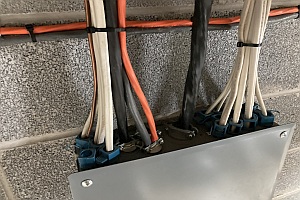
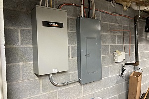
Here, the cables between the transfer switch and main panel board are shown. The homeowner determined which circuits would be powered by the generator and these were moved from the panel board and terminated at circuit breakers inside the transfer switch.
